
3D Bengal Fan - Channel-Levee System
 MTU has participated in and carried out several research expeditions to the Bay of Bengal, namely SO 93, SO 125, SO 126 and SO 188. In the course, we gained a good understanding of sedimentary processes, particularly the development of channel-levee systems and the distribution of sedimentary facies related to turbidity currents such as sheeted sands, levee complexes, meander loop development and avulsions. Finally, our work led to IODP drilling expedition EXP 354 to 8°N in the Bay of Bengal to create a link between sedimentary deposits and the processes on land responsible for erosion, mountain uploift, sediment transport and monsoon intensity.
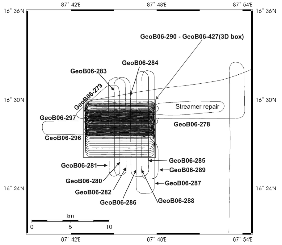
One major target of the Cruise SO 188-1 was the 3-D imaging of a prominent meander loop of the active channel-levee system at 16°29’N. The surrounding area has already been investigated with seismic and acoustic methods during Sonne Cruises SO 93 and SO 125. As one important result of the Parasound and bathymetric studies it turned out that the channel-levee system is here characterized by an unusually high number of cut-off loops, which are often completely refilled and therefore not visible in bathymetry. The SO 125 seismic data show that all these cutoff loops and the now active channel itself developed with a complex behaviour: the channel axes aggraded and migrated not only with different ratios, but changed also their behaviour during their development. As a result of this complex development, and because the turbidity currents running through the channel deposited their coarse-grained load only on the channel floor, bodies of coarse grained sediments have been accumulated beneath and aside the channel axes. However, the existing profiles have revealed only a 2-D picture, but it is obvious that the above described development and the resulting architecture could be figured out only by a 3-D structural analysis.
To study the channel development, the most prominent loop of the active channel was chosen as working area. For the 3-D survey, the streamer was split into two parts of 300 m active length each and two GI Guns were towed beside the ship. Using this geometry a profile spacing of 32.5 m was needed for a 3-D study. To realize this coverage, a profile grid of W-E and E-W lines, connected by curves as tight as possible for the towed equipment, was designed. By moving these loops several times south- and northwards, the desired line spacing was finally reached in the central part of the study area. In the end, seismic data were collected along 137 profiles within 6 days and 6 hours.

